

PLC Control System in DMF Recovery

1. Process Overview: What is DMF Recovery?
DMF is a common industrial solvent. Due to its cost and environmental regulations, it is often recovered from waste streams (e.g., from pharmaceutical or synthetic leather industries) rather than disposed of.
The most common method is Distillation:
- Feeding: The waste DMF mixture is pumped from a storage tank into a distillation column.
- Heating: The mixture is heated in a reboiler. DMF has a higher boiling point than water and many other impurities.
- Separation: Impurities (water, low-boiling-point compounds) are vaporized, travel up the column, and are condensed in a condenser, collected as "light ends" or wastewater.
- Collection: The purified DMF is drawn off from the bottom of the column and sent to a clean DMF storage tank.
- Cooling: The recovered DMF is cooled before storage.
This process requires careful control of temperature, pressure, and flow rates.
2. Role of the PLC Control System
The PLC is the central brain that automates this entire process, ensuring it runs efficiently, safely, and consistently. Its core functions can be broken down as follows:
A. Sequential Logic Control (SLC) / Automatic Batch Sequencing
The PLC executes a pre-defined sequence to automate the entire recovery cycle, moving from one step to the next only when specific conditions (permissives) are met.
Typical Sequence:
- Pre-Check: Verify all valves are in their safe start positions (e.g., discharge valve closed), no emergency stops are active, and utilities (cooling water, steam) are available.
- Feed Stage:
- Open the feed tank outlet valve.
- Start the feed pump.
- Use a level transmitter in the distillation column to determine when to stop feeding (e.g., fill to 80% capacity).
- Close the valve and stop the pump.
- Heating Stage:
- Gradually open the steam control valve to the reboiler.
- Execute a Temperature Ramp Control to heat the mixture at a controlled rate to avoid thermal shock or bumping.
- Distillation & Reflux Phase:
- Monitor column temperatures (multiple sensors at different trays).
- Control the reflux ratio by timing the operation of the reflux solenoid valve (e.g., open reflux for 60 sec, divert product for 20 sec). This is critical for purity.
- Product Collection:
- Once column temperatures stabilize indicating pure DMF vapor is present, open the product outlet valve to the clean DMF tank.
- Control flow based on level in the clean tank or a calculated rate.
- Shutdown & Purge:
- Upon completion (or if a fault is detected), close the steam valve.
- Execute a cooldown sequence, perhaps by circulating cooling water.
- Purge the system with Nitrogen (N₂) to prevent explosive atmosphere formation (DMF vapors are flammable).
B. Continuous Process Control (Loops)
The PLC runs closed-loop PID algorithms to maintain stable process conditions.
- Temperature Control (TC): The most critical loop.
- Process Variable (PV): Temperature in the reboiler or a specific column tray.
- Set Point (SP): The desired temperature, often set by the operator or the sequence.
- Output (OP): Controls the opening of the steam control valve to add more or less heat.
- Level Control (LC):
- Column Bottom Level: Controls the DMF product discharge valve to maintain a level, ensuring the heating coils are always submerged.
- Tank Levels: Controls feed and transfer pumps to prevent overfilling or running dry.
- Pressure Control (PC): (If running under vacuum)
- PV: Column pressure.
- OP: Controls a vacuum pump or a bleed valve.
C. Safety Interlocks and Alarm Management
This is a non-negotiable part of the system. The PLC constantly monitors for dangerous conditions.
- Hardware Interlocks (Critical Safety): Often implemented with a dedicated Safety Relay or Safety PLC that is separate from the main control PLC for highest reliability.
- Emergency Stop (E-Stop) buttons: Cut power to all motors (pumps, agitators) and close main steam valve.
- High-Level Switch in column: Overrides everything and stops the feed pump to prevent overfilling.
- High-Pressure Switch: Triggers emergency venting or shutdown.
- High-Temperature Switch in reboiler: Directly cuts power to the steam solenoid valve.
- Software Interlocks (in the PLC):
- "Steam valve cannot open if cooling water flow is not proven."
- "Feed pump cannot start if column discharge valve is closed."
- "Agitator cannot run if tank level is too low."
- Alarms: The PLC triggers visual and audible alarms on the HMI for operator attention.
- High/High-High: Column temperature, pressure.
- Low/Low-Low: Tank levels, cooling water pressure.
- Deviation: Temperature deviates significantly from setpoint.
- Equipment Fault: Pump overload trip signal.
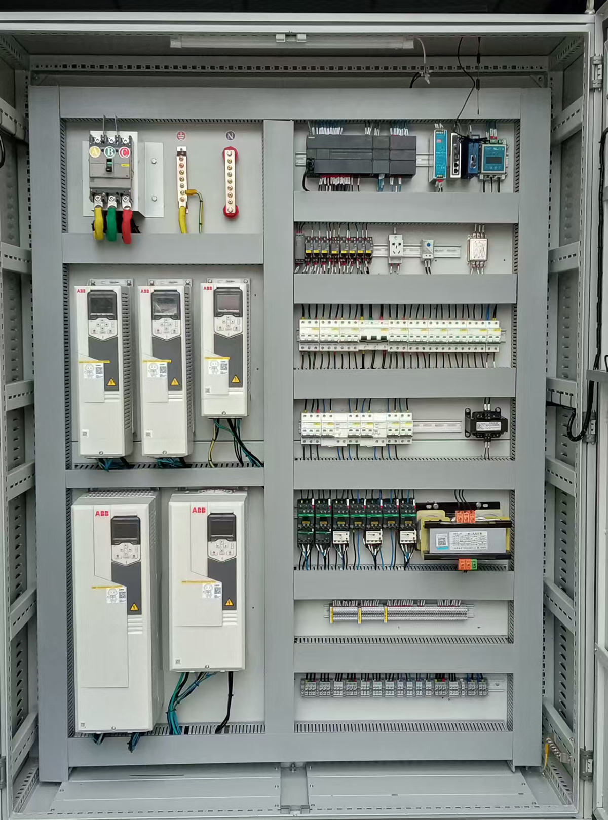
3. System Architecture & Key Components
| Component | Function in DMF Recovery |
| PLC | Central processor (e.g., Siemens S7-1200/1500, Allen-Bradley CompactLogix/ControlLogix). Executes logic, PID loops, and handles communication. |
| HMI (Touch Panel) | Human-Machine Interface. Allows operators to start/stop sequences, view trends, setpoints, and acknowledge alarms. |
| Temperature Sensors | PT100 RTDs (for accuracy) or Thermocouples (for range) in column, reboiler, condenser, and product line. |
| Level Sensors | Radar or Ultrasonic for tanks, Differential Pressure (DP) cells for column bottom level. |
| Flow Meters | Coriolis meters (can also measure density) or magnetic flow meters for conductive streams. |
| Control Valves | Pneumatic control valves with positioners for steam and coolant. |
| Solenoid Valves | For on/off control of feed, product, reflux, and purge lines. |
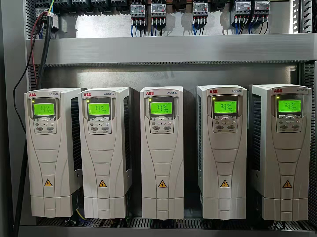
| Variable Frequency Drives (VFDs) | To control pump speeds for precise feeding and energy savings. |
| Motor Starters / Contactors | To control pumps and agitators, with overload protection. |
| I/O Modules | Digital Input (DI) for statuses (e.g., valve limit switches), Digital Output (DO) to start motors/open valves, Analog Input (AI) for sensors, Analog Output (AO) for control valves. |
4. HMI Screen Examples
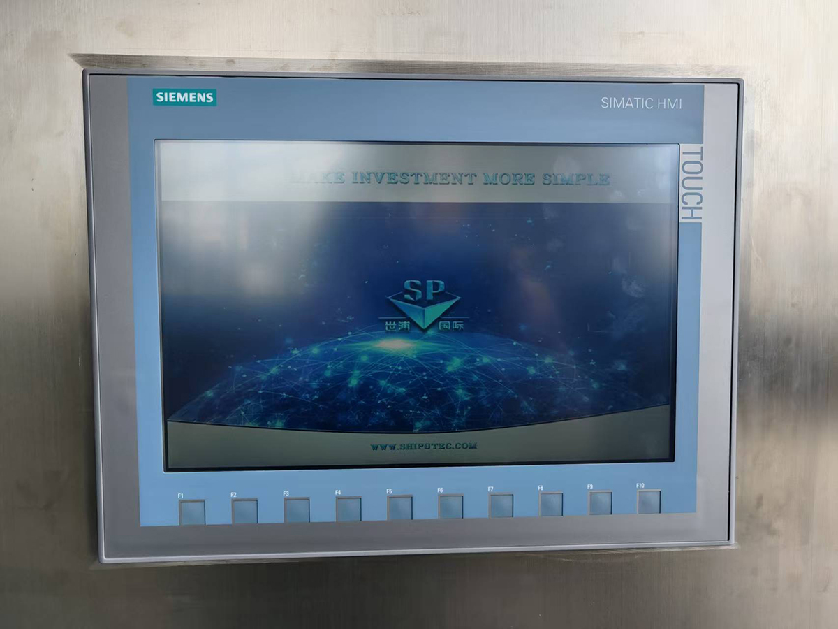
A well-designed HMI is crucial:
- Main Overview: Mimic diagram of the entire process with live values (temps, levels) and equipment status (running/stopped).
- Control Screen: Buttons for Auto/Manual mode, sequence start/stop, manual override for each valve and pump.
- Trend Screen: Real-time graphs of key parameters (Temp, Pressure, Flow) to monitor process performance and troubleshoot.
- Alarm Summary Screen: A live and historical list of all active and past alarms with timestamps.
- Recipe Management: (For different waste streams) Ability to save and load different setpoints for temperature, reflux ratio, etc.
5. Key Design Considerations
- Explosion Proofing: DMF vapors are flammable. Equipment in hazardous areas (near tanks, columns) must be rated for the appropriate zone (e.g., ATEX, IECEx). This includes using intrinsically safe (IS) barriers for field instruments and explosion-proof enclosures.
- Material Compatibility: Sensors and valves in contact with DMF must be made of compatible materials (e.g., stainless steel 316, PTFE seals).
- Redundancy: For large, continuous systems, a redundant PLC and power supplies might be considered to avoid production stoppages.
- Data Logging: The PLC should log all process data and alarms for quality tracking and regulatory compliance.
Conclusion
Implementing a PLC control system for DMF recovery transforms a manual, hazardous, and inconsistent process into an automated, safe, and highly efficient one. It ensures product quality (purity), maximizes recovery yield, minimizes energy consumption, and provides a comprehensive record of operation for safety and audit purposes. The initial investment in the automation system is quickly recovered through operational savings and reduced risk.
Related products
-

DMA Treatment Plant
Main Features During the DMF rectifying and recovery process, due to the high temperature and Hydrolysis, parts of the DMF will be disintergrated to FA and DMA. The DMA will cause odor pollution, and bring serious impact for the operation environment and the enterprise. To follow the idea of Environment protection, the DMA waste should be incinerated, and discharged without pollution. We have developed the DMA wastewater purification process, can get about 40% indus...
-

DMAC Solvent Recovery Plant-New Technology
MAC, as an excellent polar solvent, is widely used in polyurethane, pharmaceuticals, pesticides, high molecular membranes (such as PVDF), and electronic chemicals. However, DMAC has certain toxicity and poor biodegradability, and its waste liquid must be effectively treated and recycled. Traditional recovery methods (such as ordinary distillation) have problems such as high energy consumption, limited product purity, and easy decomposition. This article will focus on...
-

DMAC Solvent Recovery Plant
Equipment Description This DMAC recovery system uses five-stage vacuum dehydration and one-stage high vacuum rectification to separate DMAC from water, and combines with vacuum deacidification column to obtain DMAC products with excellent indexes. Combined with evaporation filtration and residual liquid evaporation system, the impurities mixed in DMAC waste liquid can form solid residue, improve the recovery rate and reduce pollution. This device adopts the main proc...
-

Chemical Storage Tanks
Chemical storage tanks are key static equipment used in the chemical, petroleum, energy, food and other industries for storing liquids or gases. Their design, selection and management directly affect production safety, environmental protection and economic benefits. The following is a comprehensive analysis of chemical storage tanks, covering types, design, materials, accessories and safety points. I. Main Classification (by Use and Structure) There are many types o...
-

DCS Control System
System Description DMF recovery process is a typical chemical distillation process, characterized by a large degree of correlation between process parameters and a high requirement for recovery indicators. From the current situation, the conventional instrument system is difficult to achieve real-time and effective monitoring of the process, so the control is often unstable and the composition exceeds the standard, which affects the production efficiency of enterpri...
-

MVR in DMF recovery
MVR in DMF recovery The MVR (Mother Vapor Recompression) function in DMF (Dimethylformamide) recovery systems is a key energy-saving technology used to enhance efficiency in solvent recovery processes, particularly in industries like pharmaceuticals, chemicals, and synthetic leather manufacturing, where DMF is widely used. Role of MVR in DMF Recovery Plant Energy Efficiency Traditional distillation for DMF recovery consumes significant energy due to high boiling p...